Installation Issues
INSTALLING OUR SHIFTERS IS NOT ANY HARDER THAN INSTALLING THE FACTORY MECHANISM. The technical level of difficulty is the same as installing the OEM shifter except that the clearances are tighter. Also because we only supply you with complete mechanisms and not individual components, installation will take longer for our shifters than for partial mechanisms that may be sold by different suppliers. On a component per component basis you will be spending about the same amount of time regardless of the origin of the product. In the past we tried to supply a step by step instructions which you can still download here but there are so many models that our instructions have become if not obsolete then too generic to be of use. BUT...
Car Specific Instructions are available on the net
We stumbled on this surfing the net:
https://www.newtis.info/tisv2/a/en/
Each model repair instructions including replacing the mechanism is outlined quite well. Sometimes the instructions appear a bit beyond the reach of a newbie wrench and in this case best leave it to a professional. These folks will typically charge between one hour or two to do the job although we can think of a few models that require more time.
As an example of these instructions here is a partial instruction for the e36M3
However
Sometimes our models differ from the OEM product in the way they connect. Click here to go to a section that shows these idiosyncrasies.
Still
This is our latest attempt at generic installation instructions.
These instructions include photos and procedures relating to modern and older models. Also included are suggestions as to how to approach the job and tips and tricks relating to the more annoying operations. Links to downloadable files and unpublished You Tube videos are also provided.
If you need more information click here to send an email requesting more details on a particular procedure. We may be able to help.
Please indicate the row and the clolumn
Installation of a Shifter Mechanism in a BMW
These steps are generic steps and should be helpful for all BMW cars. Most of the pictures are from e36M3 and e46M3 some e9X, 2002 and e28s.
When replacing the Shifter Mechanism, you will need to work from inside the car and underneath the car. So here goes. And the pdf download of this section
Foreword
Regardless of what you may have heard, there is no way to install a shifter in a BMW without going underneath the vehicle. Unlike many Japanese and American cars the shift lever in a BMW is not bolted to the top of the transmission. The lever that you see in the passenger compartment traverses a bracket located below the vehicle and is secured below the bracket with a clip. So at the very least that clip must be released. To be fair it is possible to replace the lever on a Z3 but one is operating blindly using all sort of contraptions wires and pliers that the operation is more an exercise in dexterity than an installation method.
As such unless you are able to raise the car on Jackstands and have a reasonable collection of tools this is a job best left to a professional. In our opinion the car should be raised about 16 inches and hand tools should include a collection of 3/8 and 1/2 Metric sockets ranging from 10mm to 19 mm and the corresponding combination wrenches. In addition a few screwdrivers, picks and pliers will be of use.
Air tools and a lift are not necessary. If you are working on a driveway with jackstands, corrugated cardboard, provides a nice and insulated surface to lie upon and is in our opinion preferable to using a creeper but to each his own.
Safety First
Flat hard surface. Don't attempt this in a sloped driveway. Don't support the car using hydraulic jack or the like. Or the vehicle Jack. Or concrete cinder blocks or anything that is not specifically designed to hold a car for repair purposes. Make sure the vehicle is properly supported. Use proper procedures when disconnecting and reconnecting fasteners. Do not stand under a part that you are disconnecting. Do not work on a hot vehicle. Read safety procedures published in every car manual.
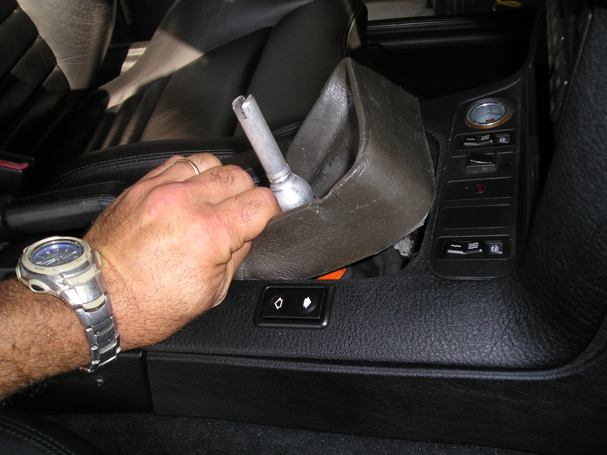
Push on the sides of the boot and lift up to disconnect the bottom of the boot from the shift console
Now grab the shift knob and yank it up. A hard jerk rather than a hard pull is needed to unclip the knob. TIP: warm the knob assembly with hair drier
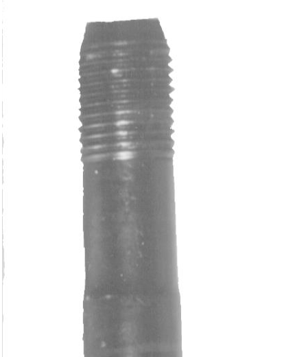
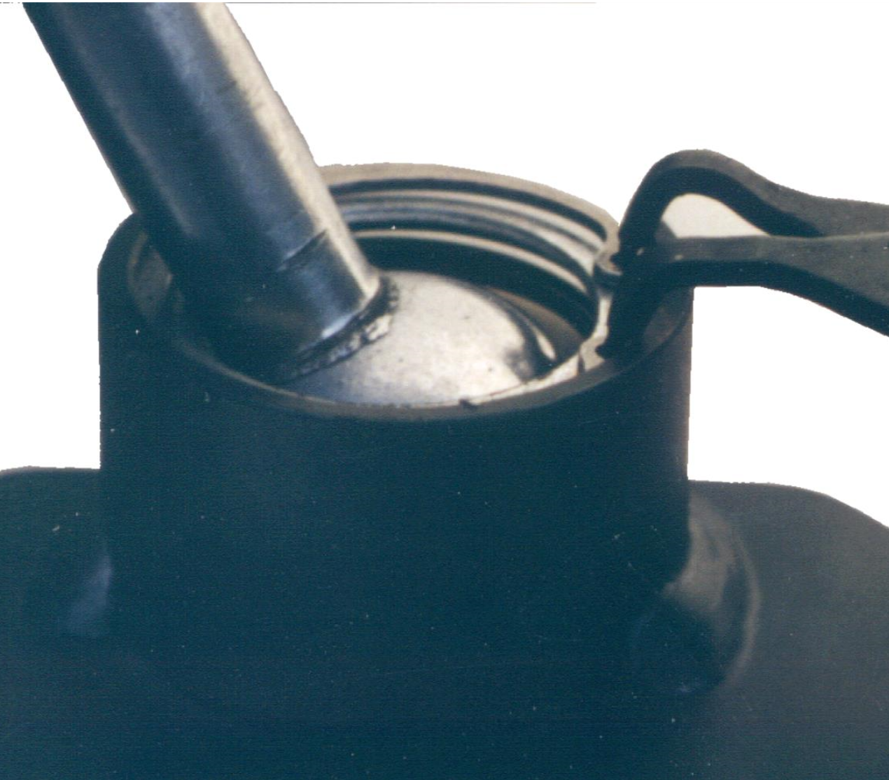
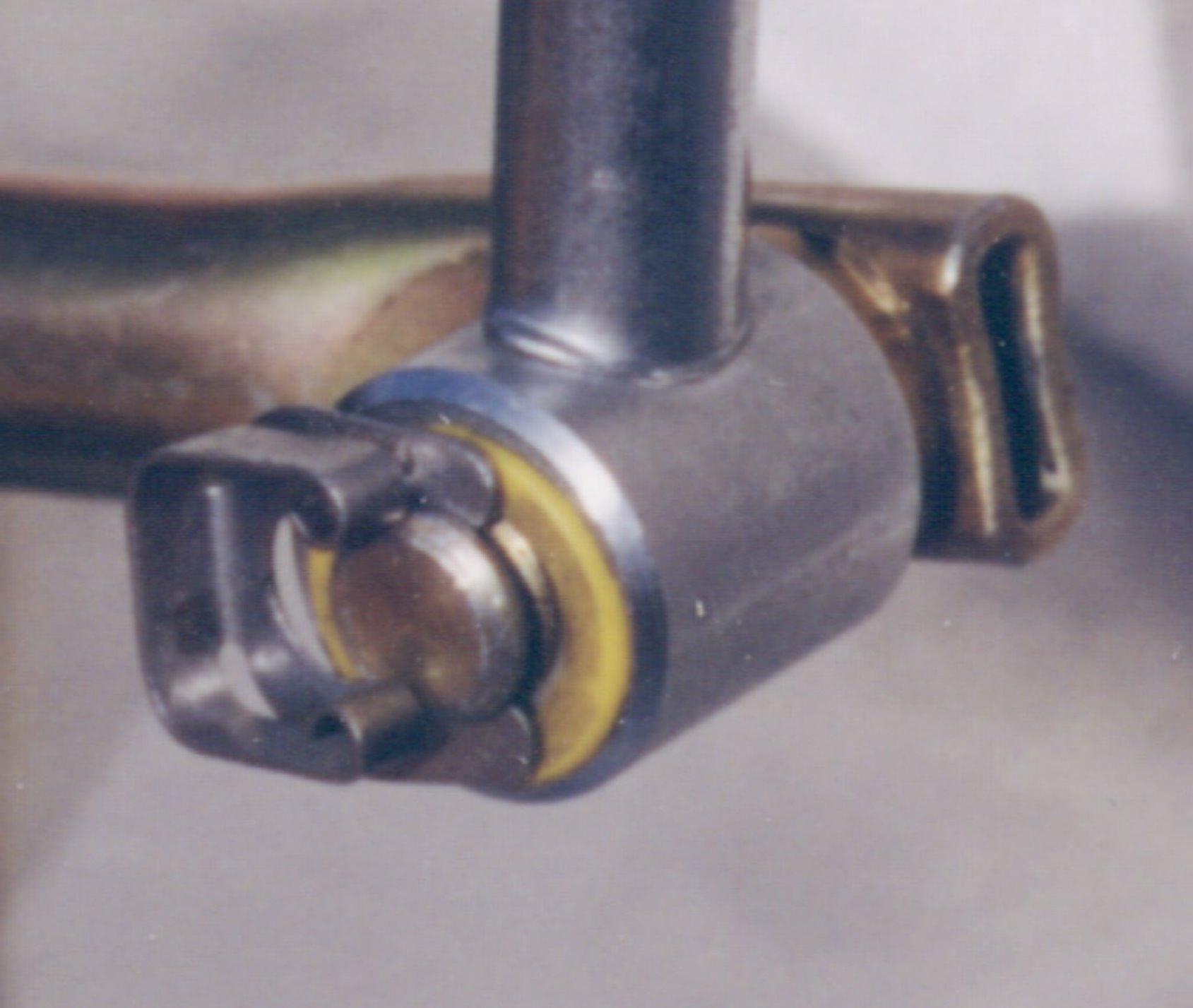
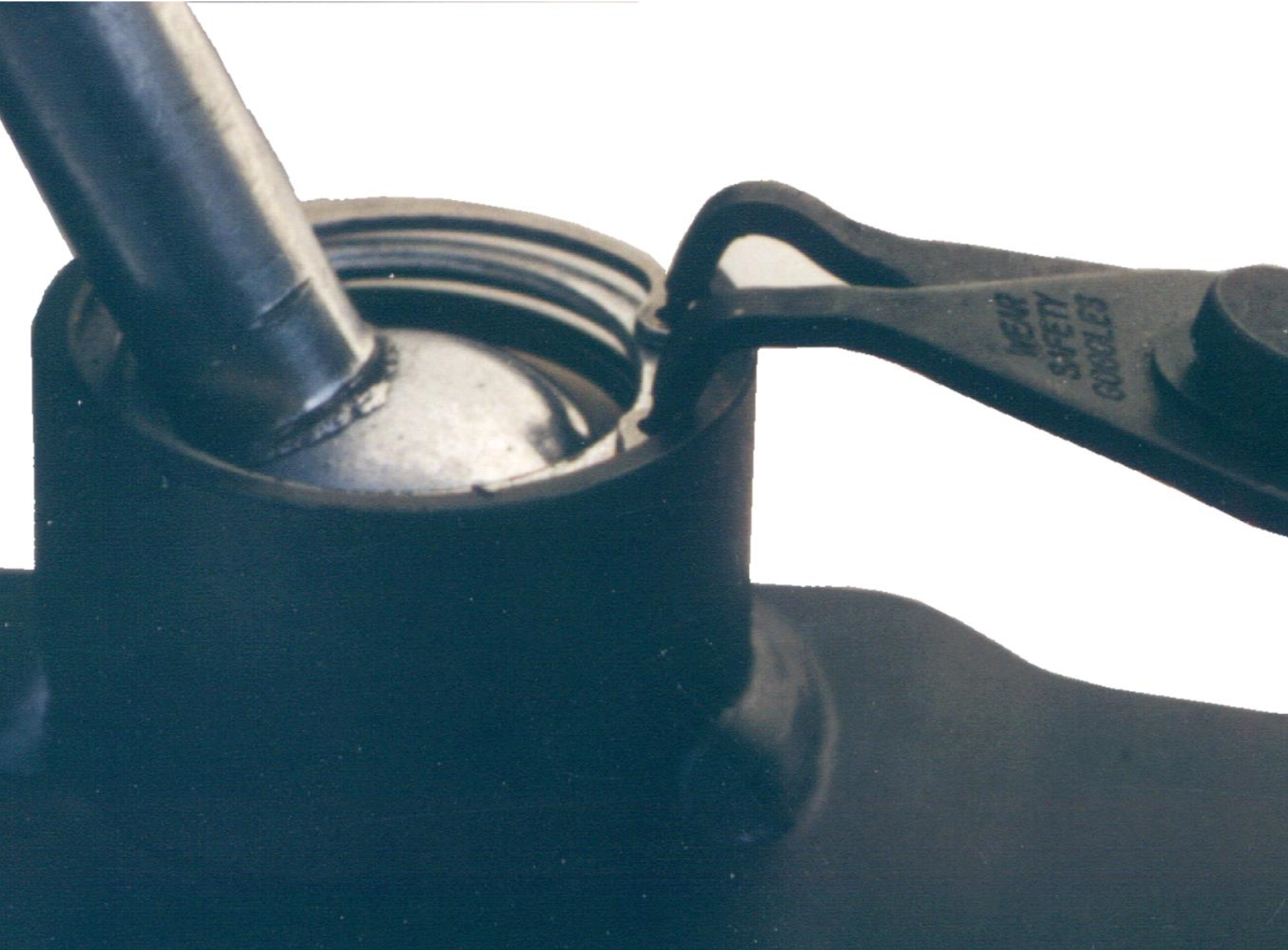
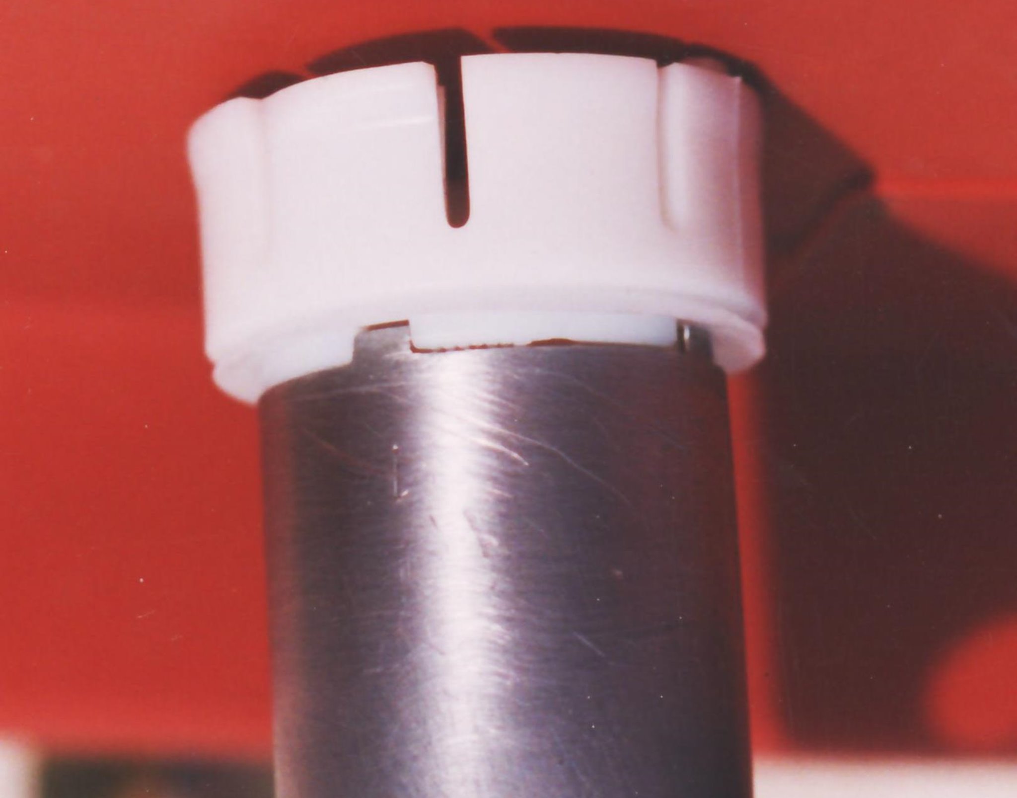
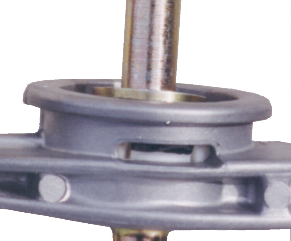
Why a hard Jerk? The knob has plastic teeth that grab around the groove indicated in this photo. Heat the knob with a hair drier to make the plastic pliable. A pull will likely not do. A strong jerk will.
This is another view of the groove in question
This is another view of the groove in question
Pre 1982 cars, the knob unscrews. Lefty loosey, righty tightey

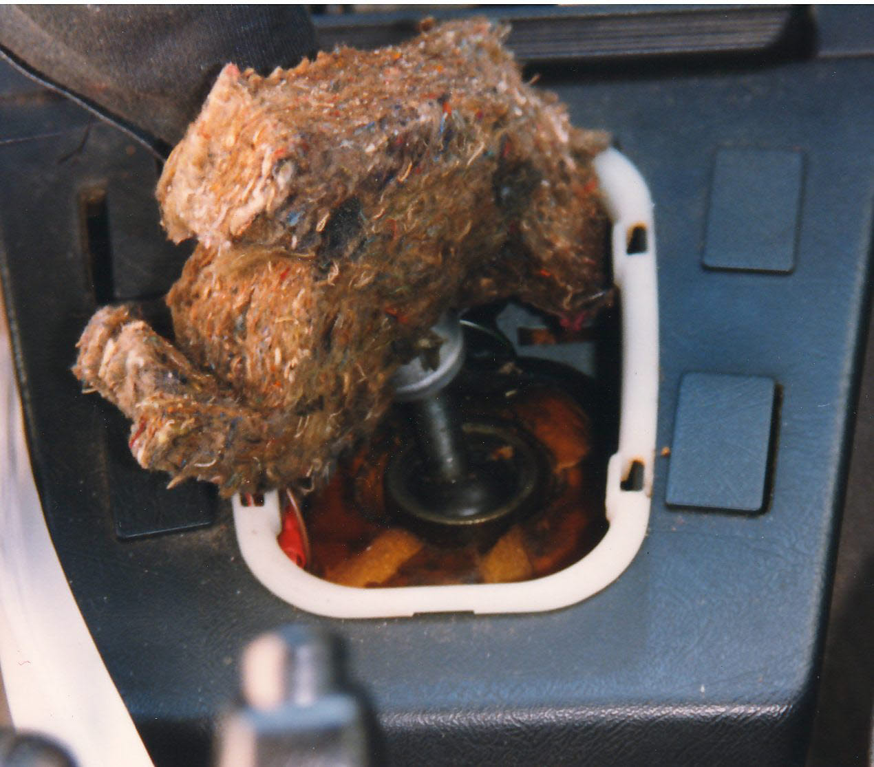
Knob and boot out. See the foam piece inside the console
Remove it

Below the foam piece is a inner rubber boot. remove it by disconnecting it from the sheet metal body and sliding it up the lever. Lubricating it generously with WD 40 or the like helps.

It helps to understand how that boot attaches . The sheet metal of the transmission tunnel goes around the bottom lip. There is an arrow on the boot that points to the front of the car.
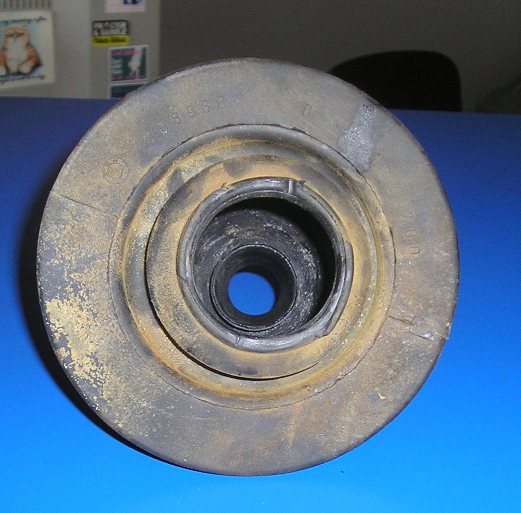
And the lever goes through the inner hole. Lubricate ,Lubricate Lubricate otherwise it might tear. Especially if your car is a senior.
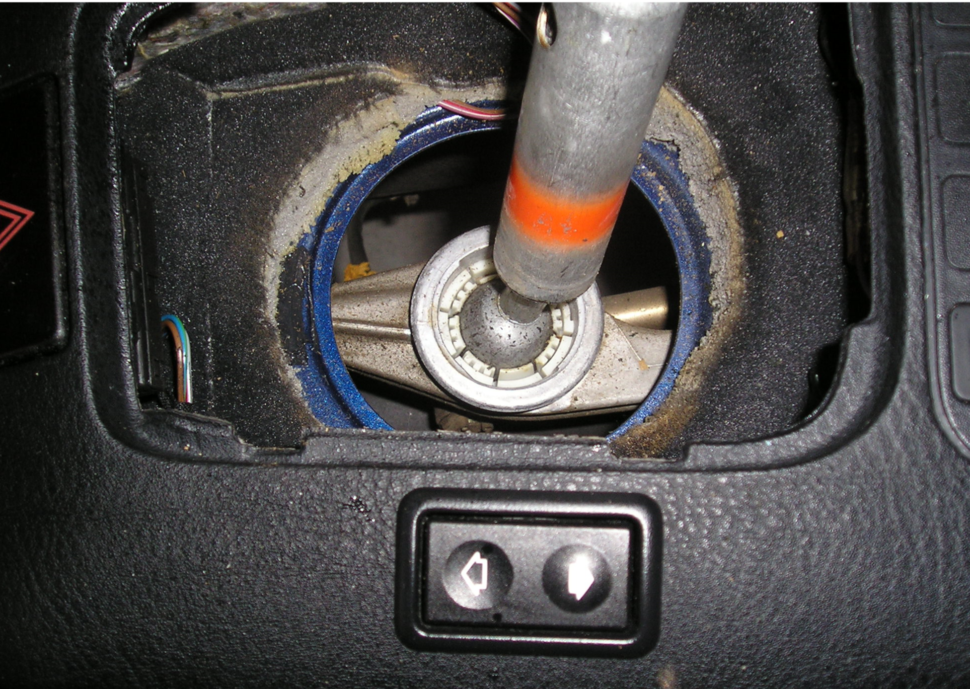
Inner boot is off. You can see the sheet metal of the transmission tunnel and the pivot ball that is holding the lever secure in the aluminium shift arm
On early cars there is not a neat foam piece but a fiberglass blanket of some sort. Remove it delicately.
On early cars the lever is held by a circlip. don't disconnect quite yet.
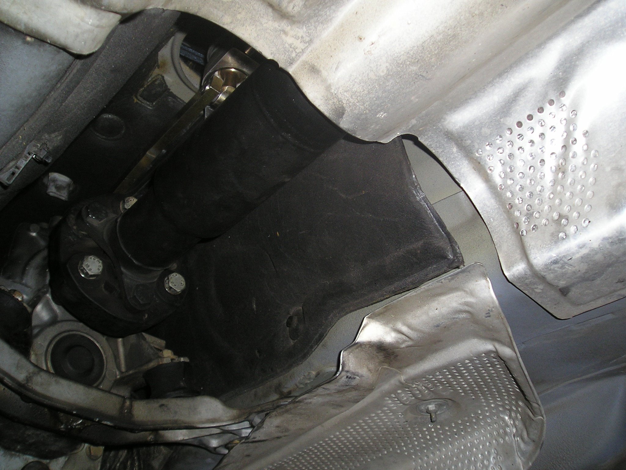
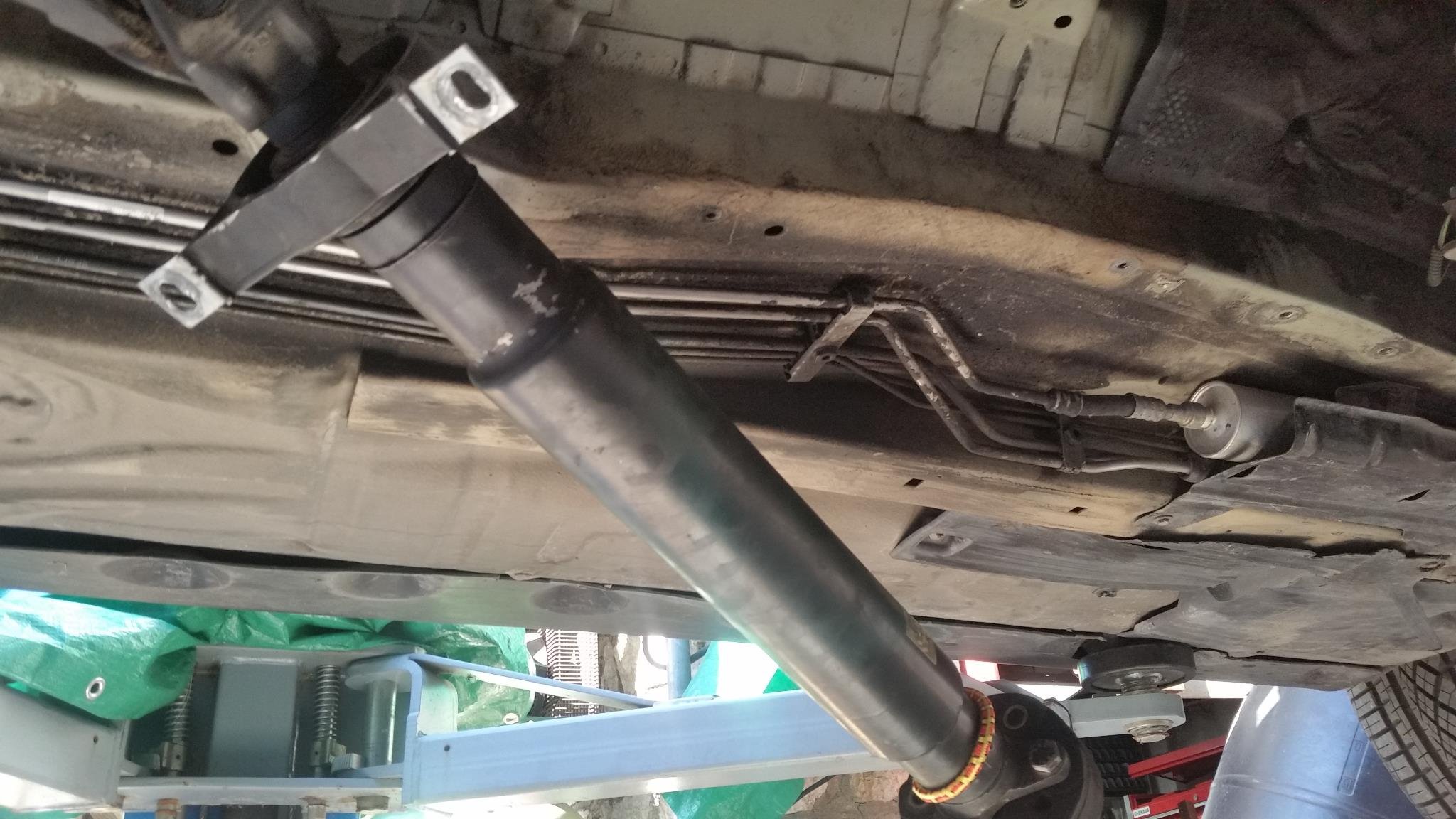
Underneath the car you can see the shifter. The exhaust has been removed for clarity . The shifter is connected to the rear of the transmission above the heat shield and driveshaft
Here is a view of everything that is in the way. exhaust, heat shield driveshaft and transmission cross member. The shifter is located in the gap between the transmission support and the bend right before the catalytic converter
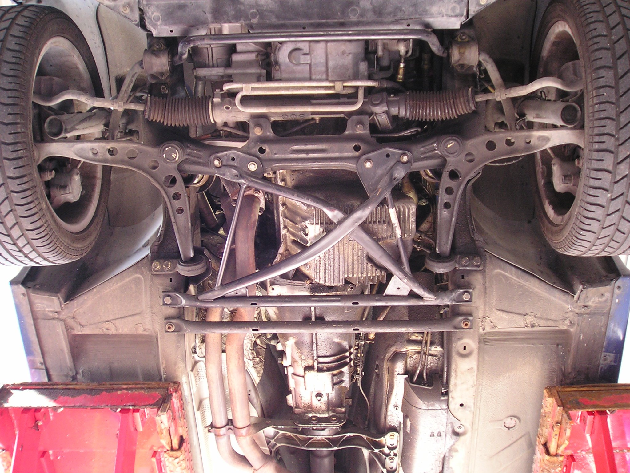
On some cars cross braces get in the way as well.
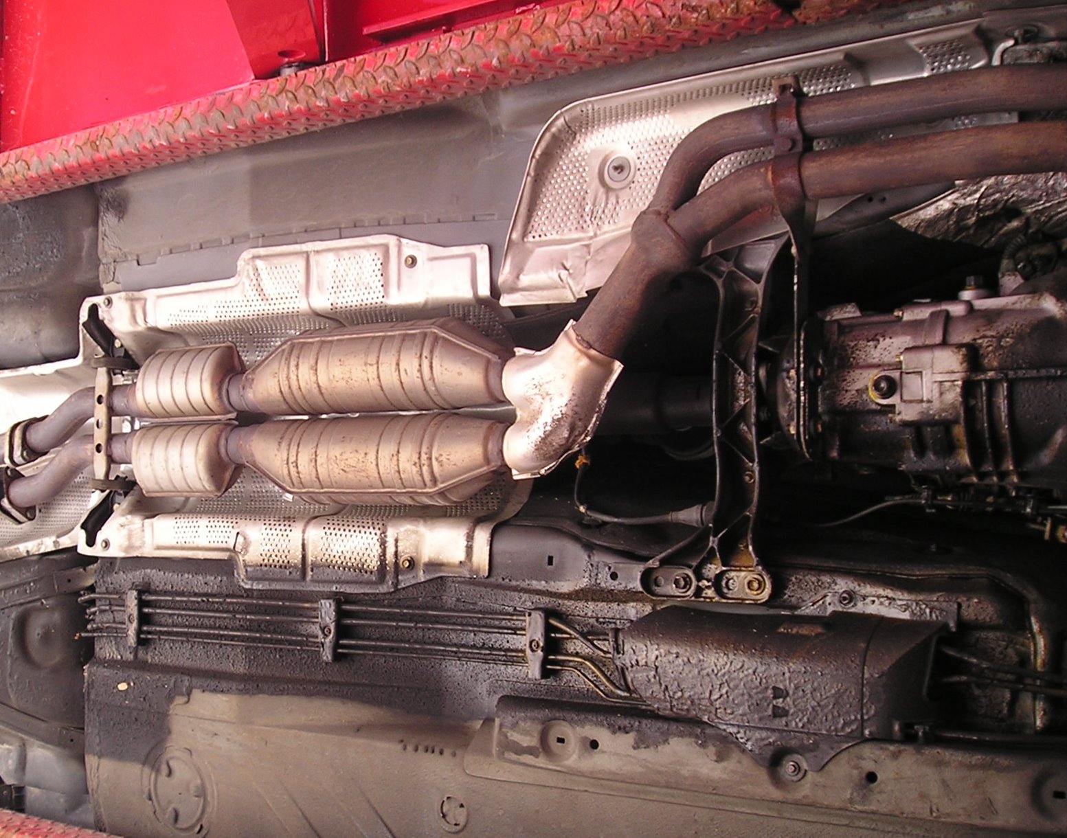
Here is the shifter assembly above the driveshaft. To reach it you need to start disconnecting stuff. Some folks remove the exhaust assembly, then the heat shield then the driveshaft, lower the back of the transmission and remove the shifter
A more minimalist approach lowers the back of the exhaust, disconnect the heat shield and sneak it around the exhaust, disconnects the front of the driveshaft and center bearing , then the transmission support and replace the shifter
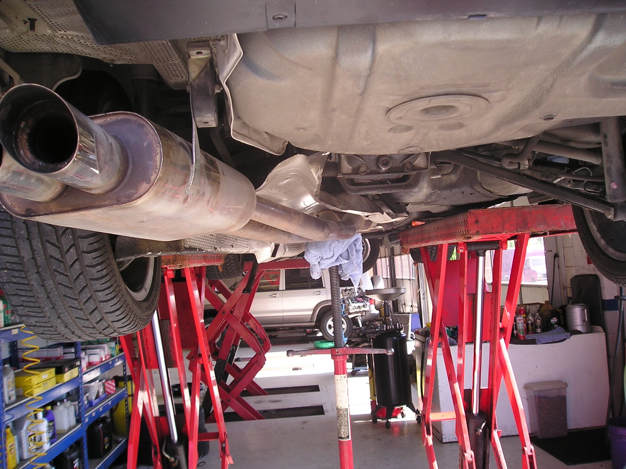
Using the minimalist approach, the exhaust has been disconnected at the muffler and partially lowered and the heat shield is snuck away.
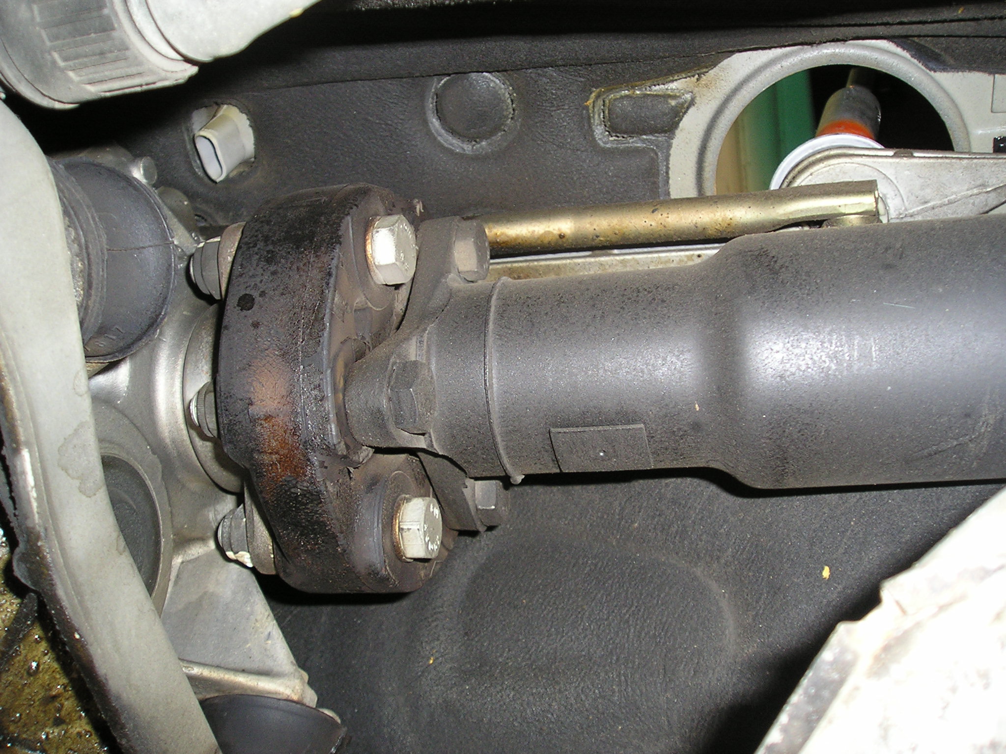
Here the driveshaft has been disconnected and swung out of the way. the driveshaft remains connected to the final drive or differential

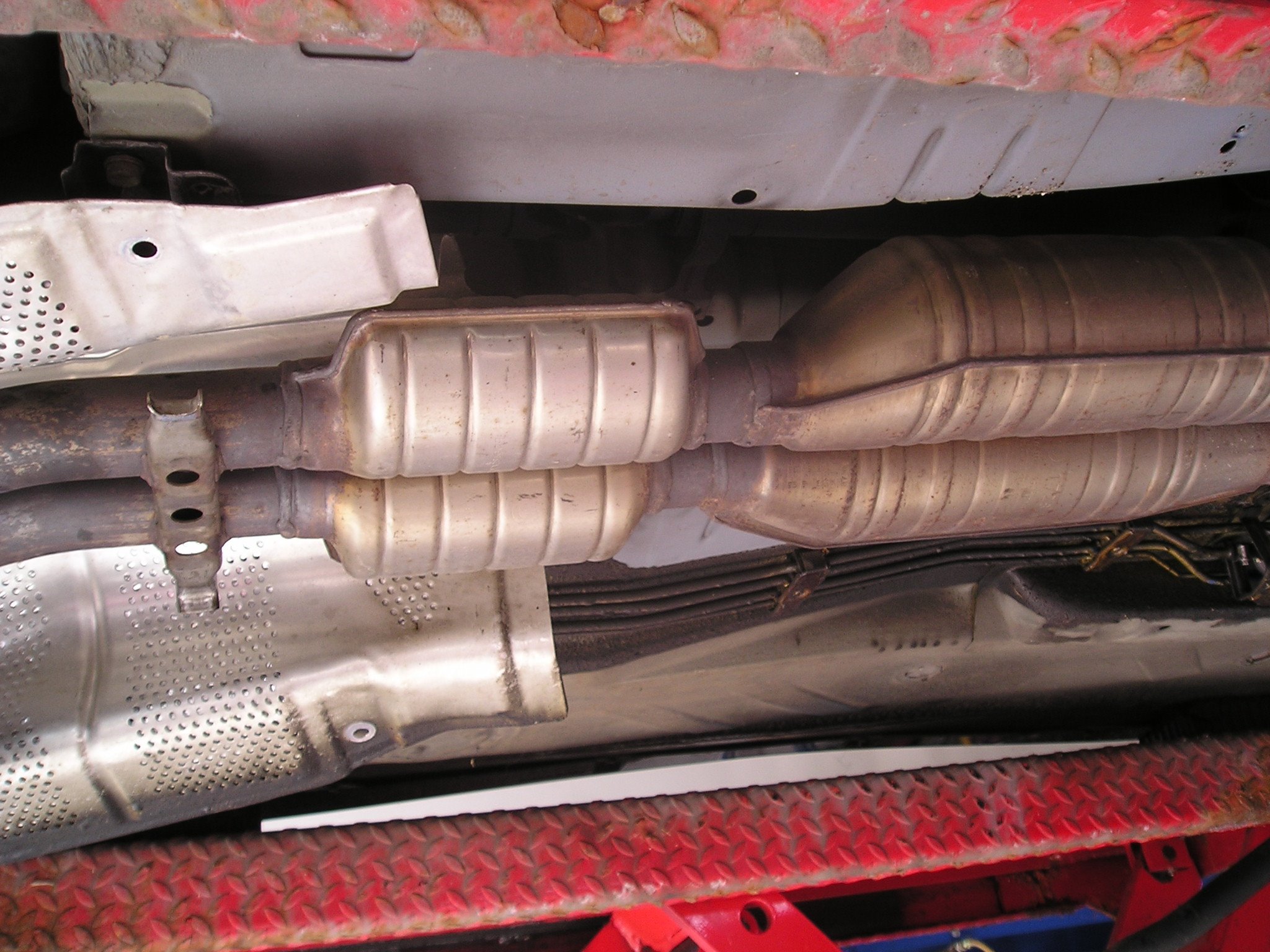
Or you can disconnect the whole assembly. Here the decision was made to remove the section of exhaust between the downpipes and the muffler. This is generally a good choice because you are dealing with 4 bolts that are easily accessible and replaceable if needs be.There is no correct or incorrect method. On a newer car it is likely easier to disconnect and reconnect complete assemblies because the fasteners are new and rust free. On older cars the minimalist approach may be better.
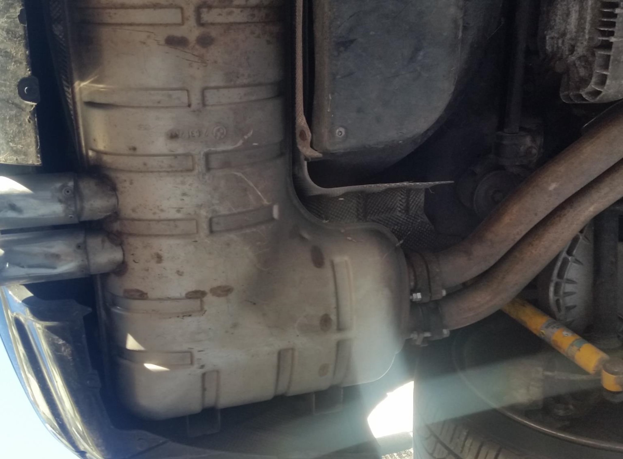
At the back the decision was made on this e46m3 to disconnect prior to the muffler and leave the muffler on the car because the weight of the whole assembly would have required a second pair of hands
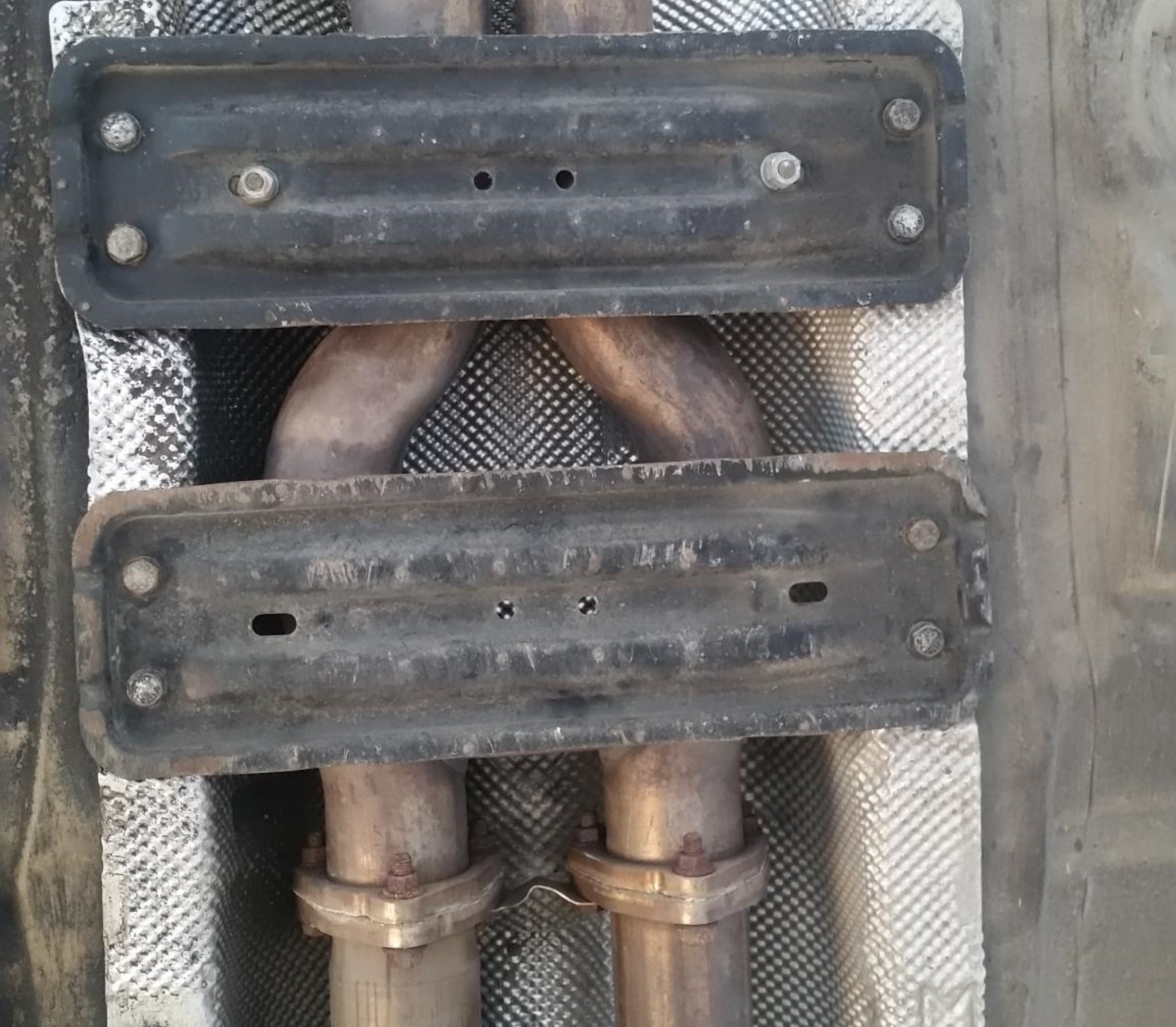
One could have disconnected the exhaust at this junction as well and end up with a much smaller section but that would have made the removal of the heat shield harder. In this particular case the braces need unbolting. typically 8mm bolts that zip right out. Keep the fasteners together with the removed part for ease of reassembly.
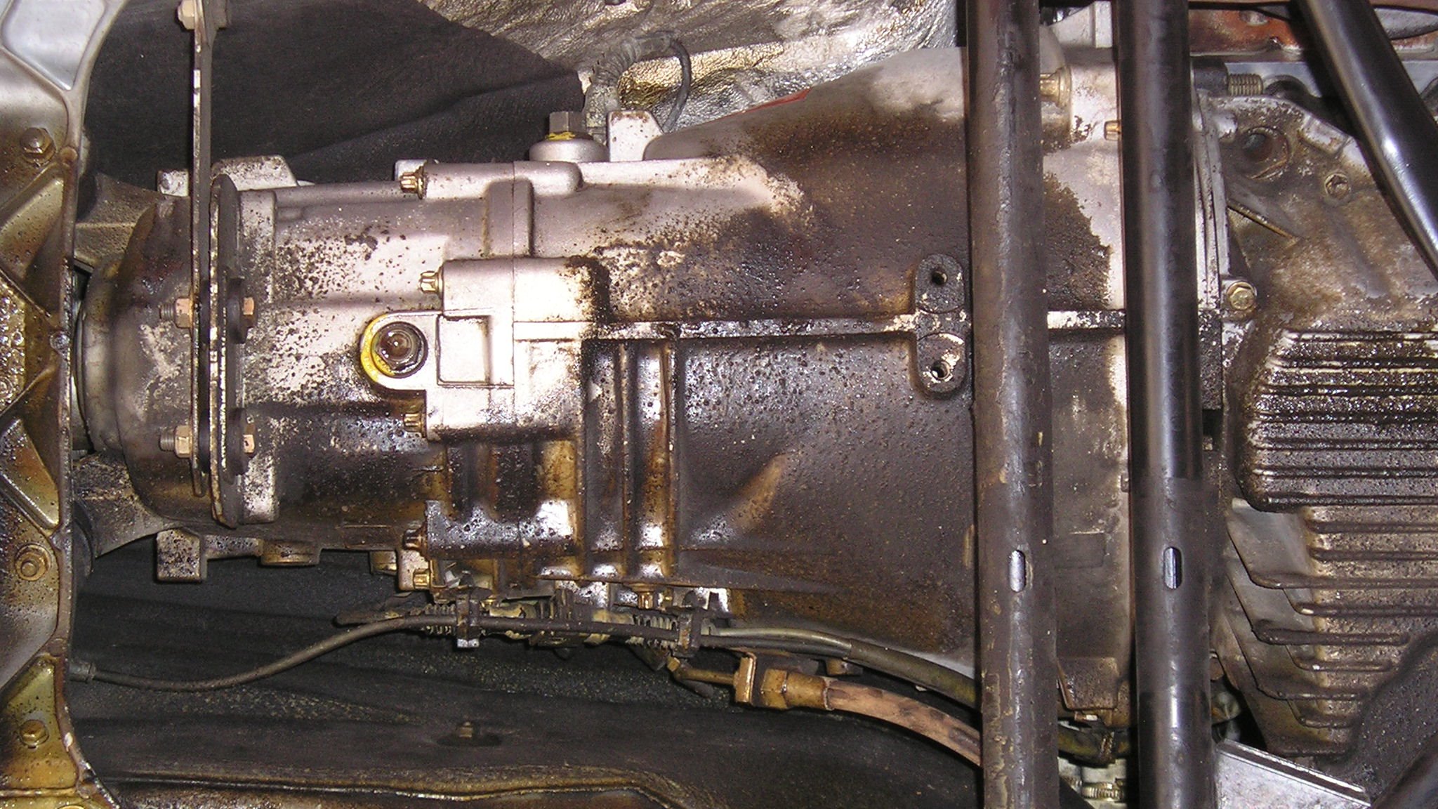
The objective is to get clear access to the back of the transmission. So after the exhaust , heat shield, crossmember and all necessary brackets are disconnected the transmission still attached to the engine will swing down by its own weight and will reveal the shifter
This is What Really Needs to Happen
You need to get a good look at the mechanism in order to remove it. You need to get some access at the top of the transmission as well as at the back of the transmission. In order for the transmission to drop low enough to access the top where the clip holding the shift arm is located the center bearing on the driveshaft needs to be disconnected. If it is not then the driveshaft will stop the back of the transmission from swinging down. You do not need to remove the driveshaft from the vehicle. Swinging it out of the way is usually sufficient. It will also help to remove the heat shield. however bear in mind that on older cars the heatshield fasteners are likely rusty and may snap. Sometimes WD40 or the like may help sometimes not. You need to decide whether to remove that heatshield or work around it on a case by case basis. Same with the exhaust. Consider the bulk and weight of the exhaust. The condition of the fasteners including the condition of the exhaust brackets when applicable. As a rule of thumb anything past model year 2000 is easier removed. prior to 2000 rust must be taken into consideration. Now lets proceed with removing and installing the actual shifter.
There are Two Kinds of Setups
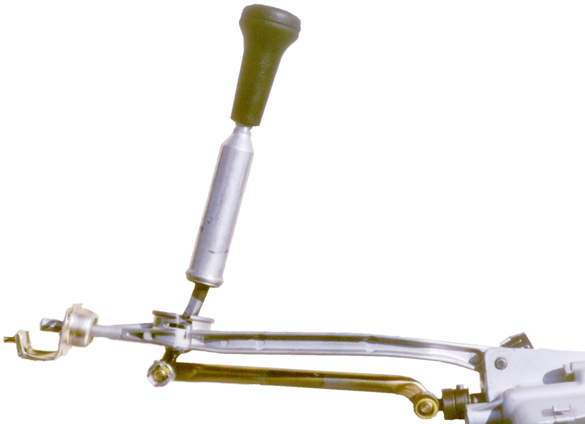
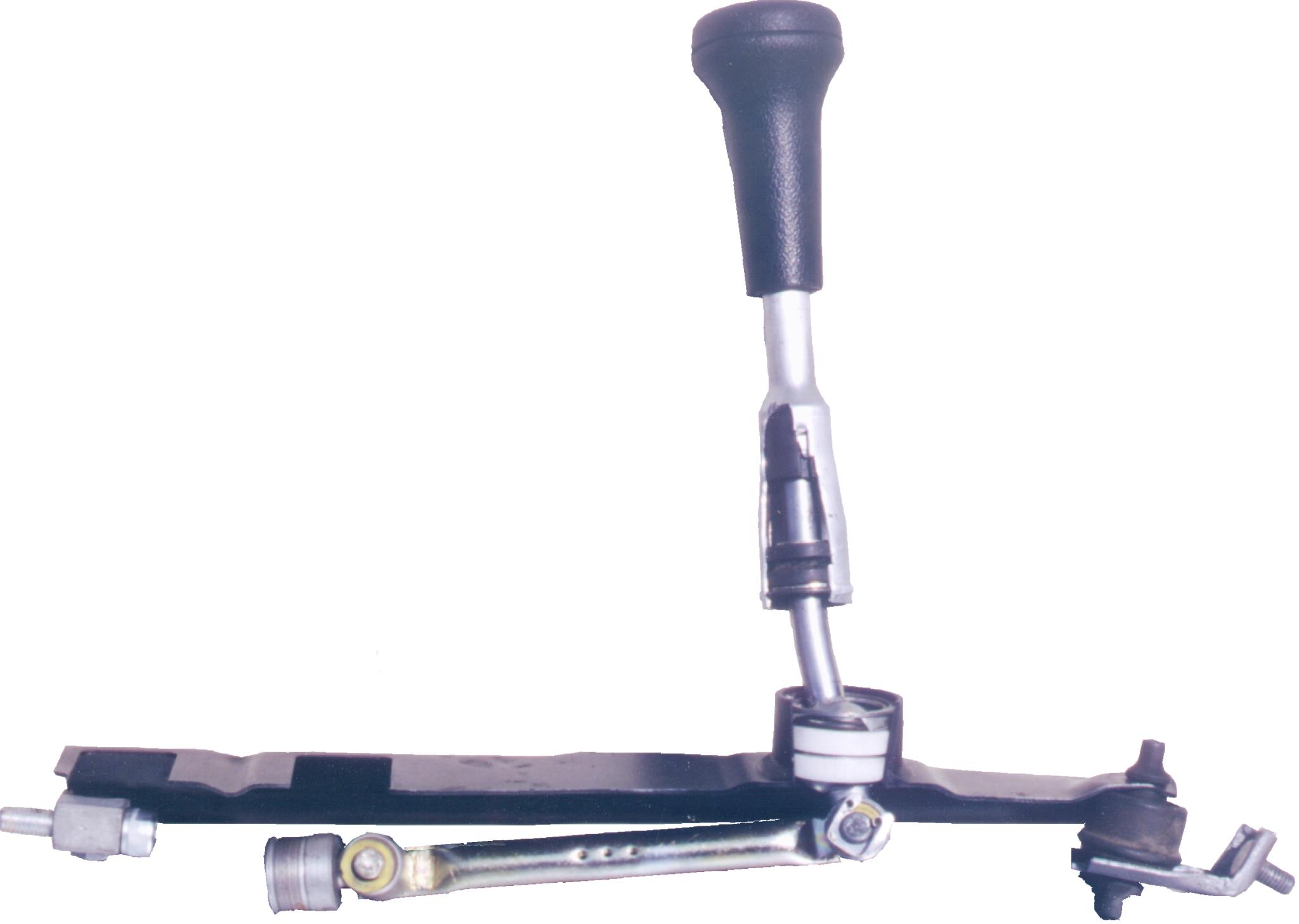
Your shifter is one of two types. In earlier cars, as shown on the right the shift arm is made of steel and connects to the transmission using at lest 2 rubber insulated aluminium bushings. On newer cars 1986 on, as shown on the left, the carrier or shift arm is made of aluminium and connects to the transmission using one or at the most 2 rubber bushings. For more details on the setup click here
Make Note of the Orientation of Your Shifter
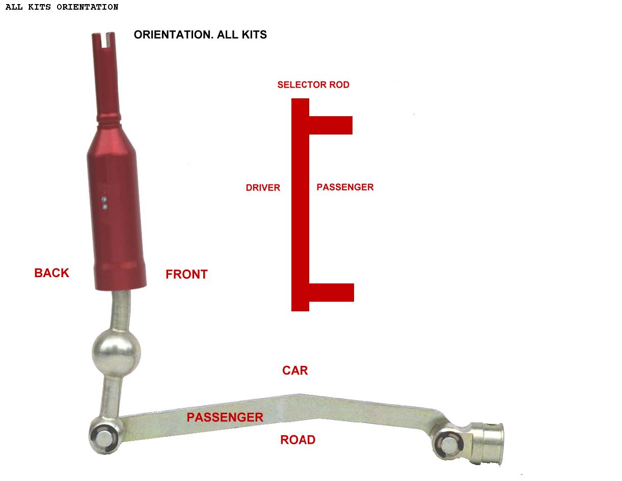
You are now ready to remove the old mechanism and install the new one. Prior to proceeding make a note of the orientation of the lever and of the position of the selector rod and coupler. The two pictures below show how 99 percent of BMW shifters are installed. If yours differs and you have the original shifter, you may be the proud owner of an exception ( e34 525 w M20 engine) . If you are unsure that you shifter is original suspect an incorrectly installed shifter and contact us so that we can confirm. OEM mechanism can in a few cases be tolerant of an incorrectly installed stock shifter but duplicating such an install with most short shifter can lead to clearance issues.
Make particular note of the orientation of the lever. It is easy to connect the lever to the selector rod 180 degrees or half a turn out of phase but the pattern will present weirdly to say the least and in some cases lead to interference issues.
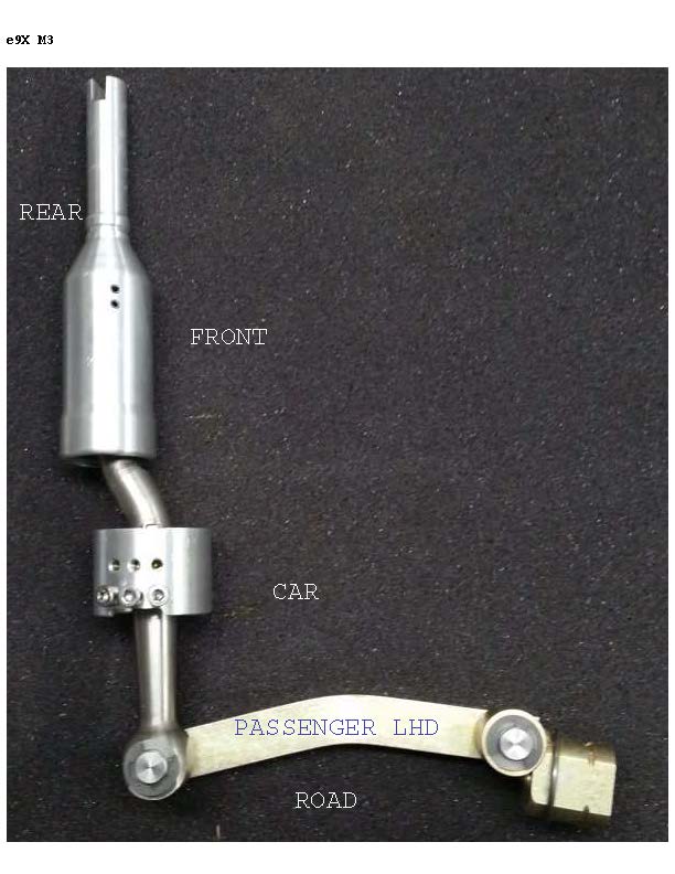
Finally if you have an e9xM3 or a late 4WD car make sure to recognize that the coupler on these cars are offset and when installing our shifter match that offset
First disconnect the clip that holds the bottom of the lever to the selector rod. Separate the lever from the selector rod
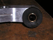
Now you can remove the shift lever. On older cars which have a steel shift arm a clip holds the lever in place

On older Models the clip compresses a spring that holds a half bushing against the pivot ball. The second half of the bushing stays in the shift arm and is reusable with our shifter.
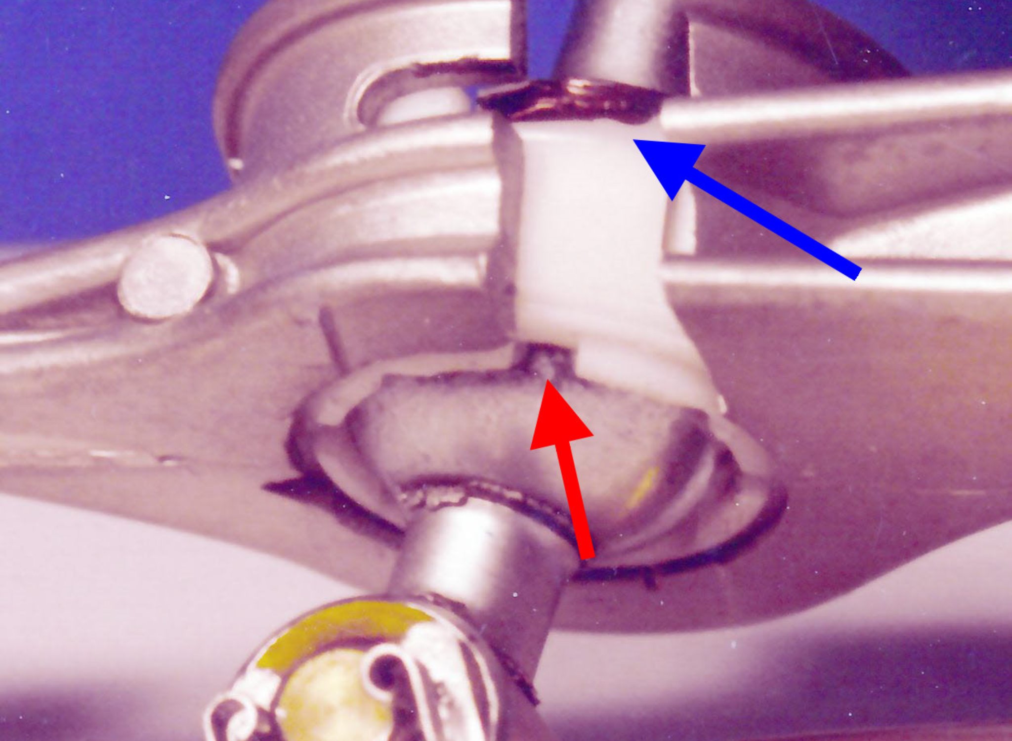
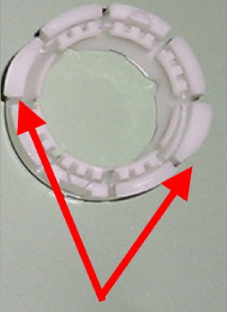
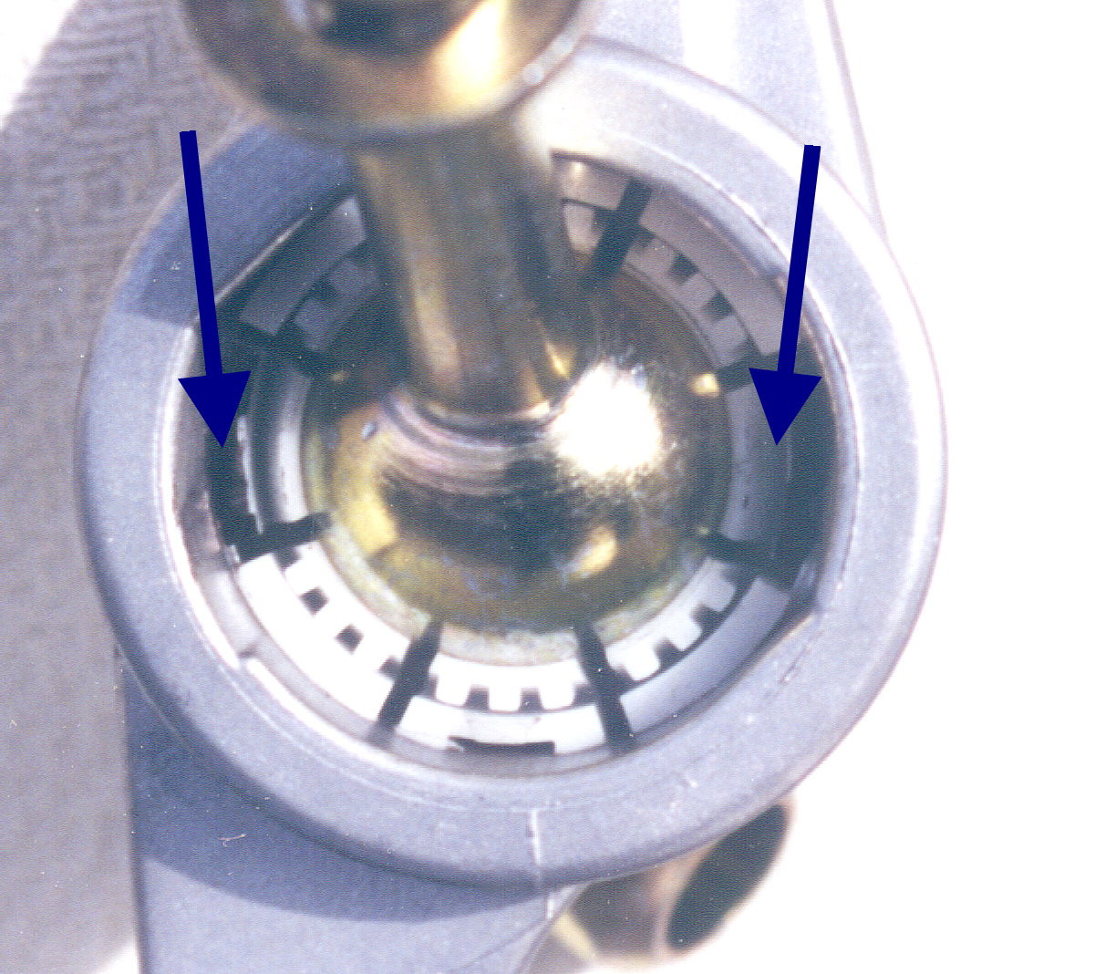
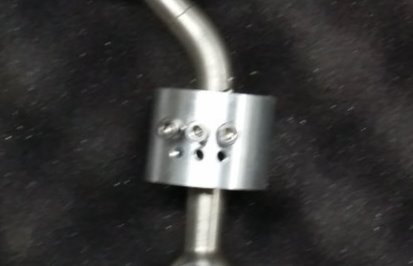
On newer models the pivot ball is held in place with a one piece bushing. That bushing has 2 tabs (blue arrow) that engage into cutouts in the shift arm. these tabs hold it in place. To release the tabs the bushing needs to rotate about 30 degree clockwise when looking from below
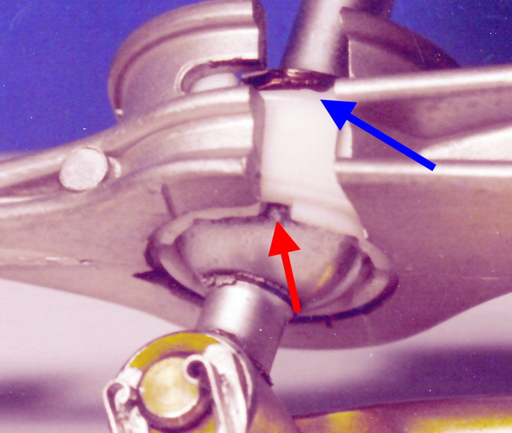
To rotate the bushing use the special tool or equivalent. Tines on the tool engage the cutouts at the bottom of the bushing and much like a socket allow it to exert the torque necessary to rotate the bushing and disconnect it
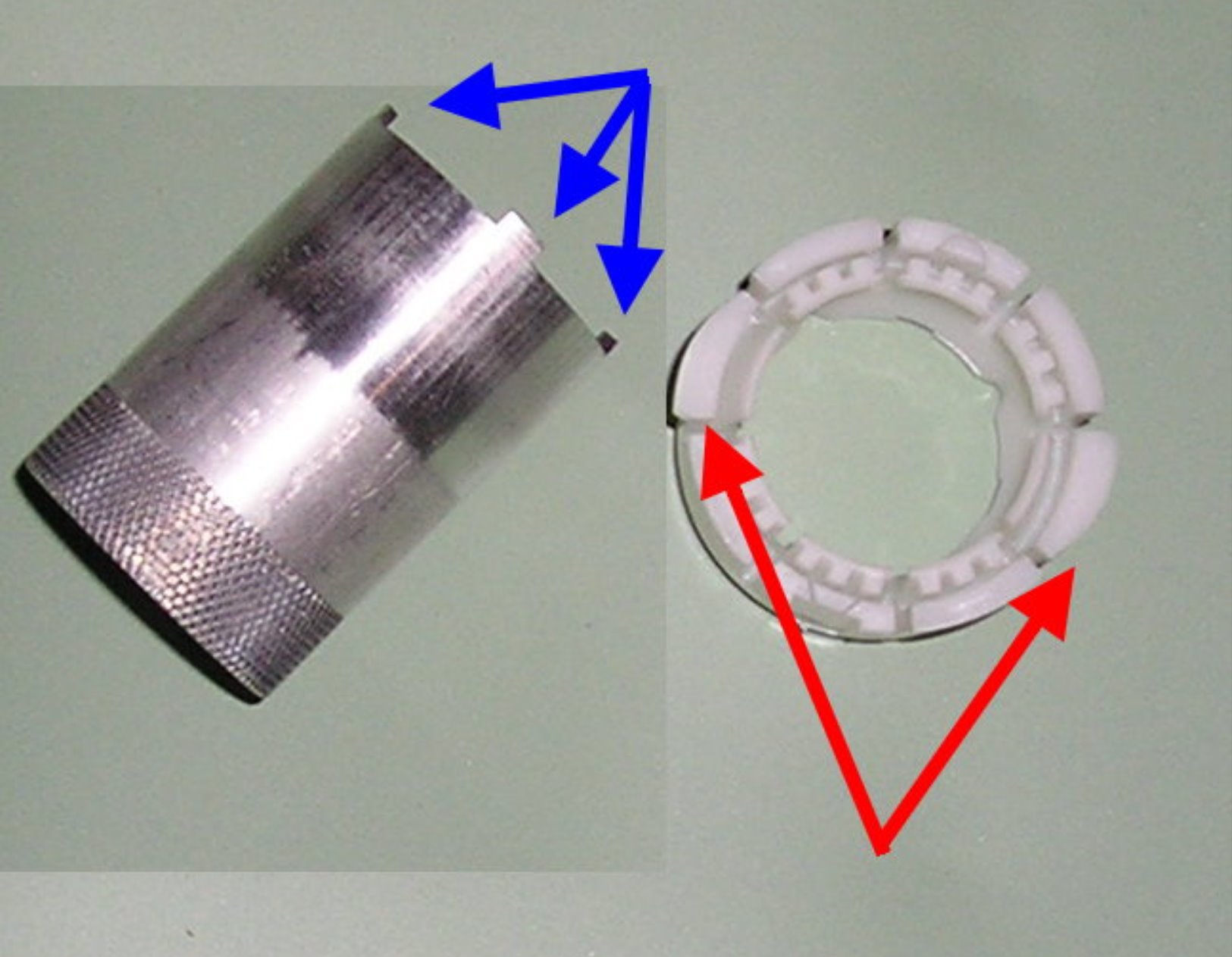
This the tool with three of four tines showing (blue arrows) and the bushing with the two tabs that need rotating (red arrows)

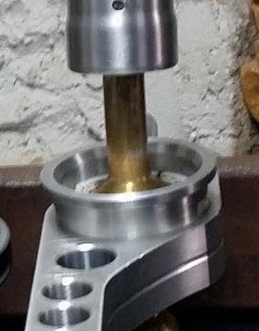
position the tool over the bottom part of the lever and make sure the tines engage the cutouts (arrow). While pushing up rotate the tool 1/4 turn. The bushing and lever will pop out of the shift arm
Sometimes the bushing bonds inside the shift arm. WD40 or equivalent helps. Note that this is a generic special tool and can be modified by you to fit your application. For more information on this special tool click here

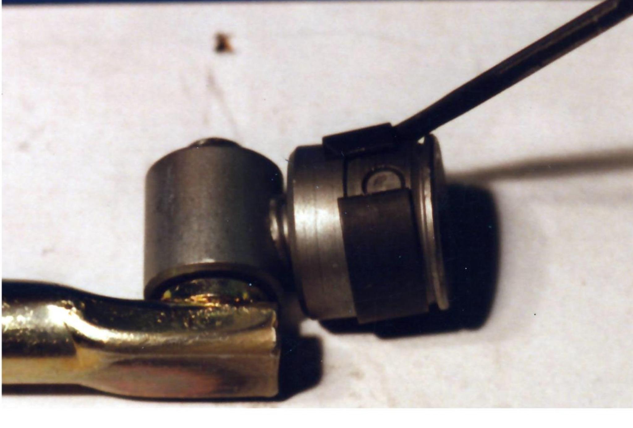
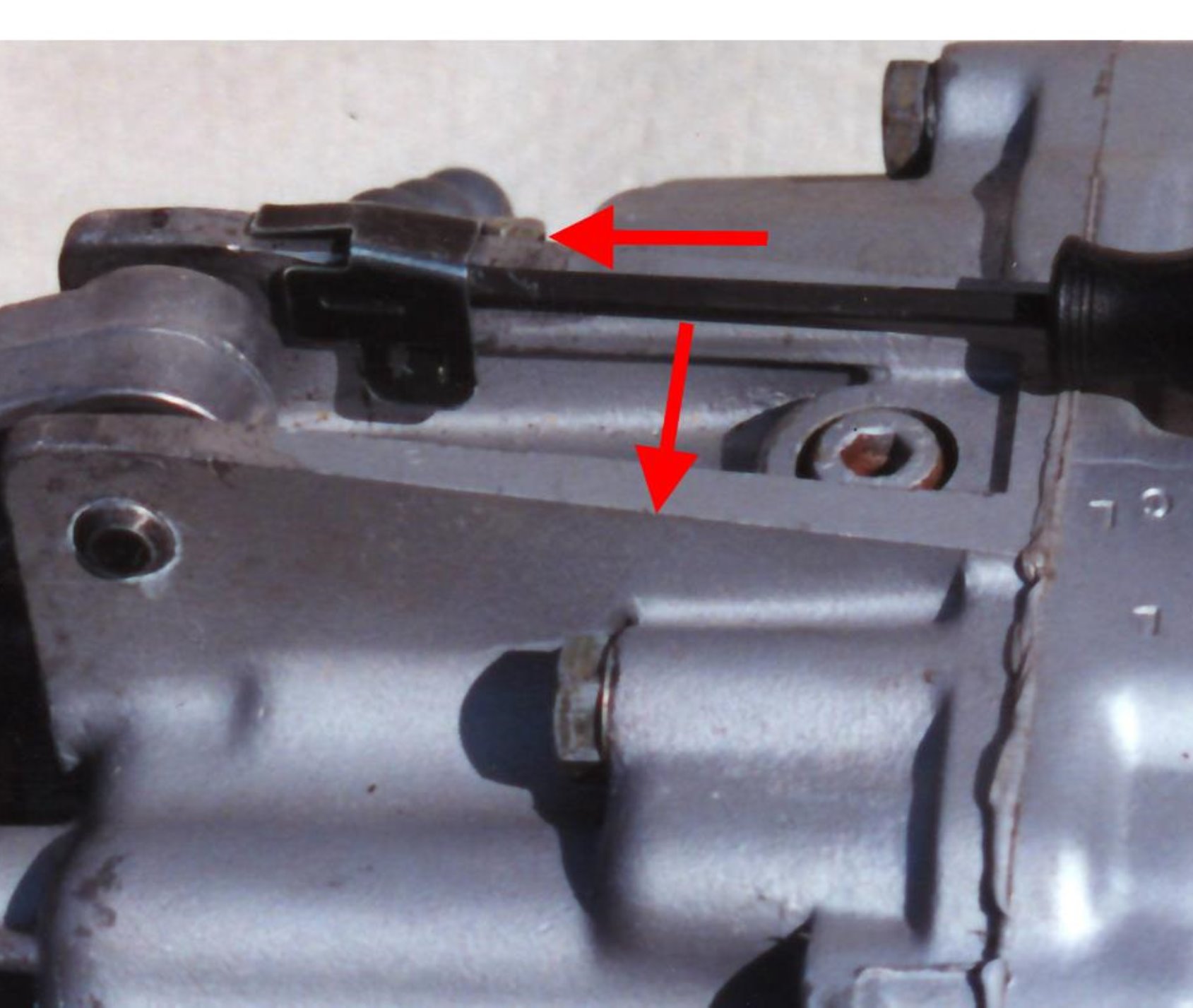
Now remove the selector rod assembly. In some cases you will need first to disconnect the selector rod from the coupler in the same fashion as when disconnecting the lever from the rod. In most cases disconnecting the coupler will allow you to remove the whole assembly. In several models you will need to disconnect the shift arm prior to disconnecting the coupler.

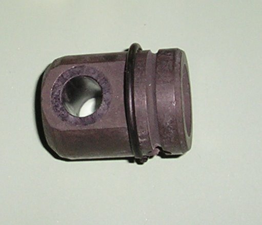
To disconnect the selector rod coupler assembly the hardened pin shown in the above picture needs to be pushed up or down. however it is retained using a spring clip which needs to be pushed out of the way
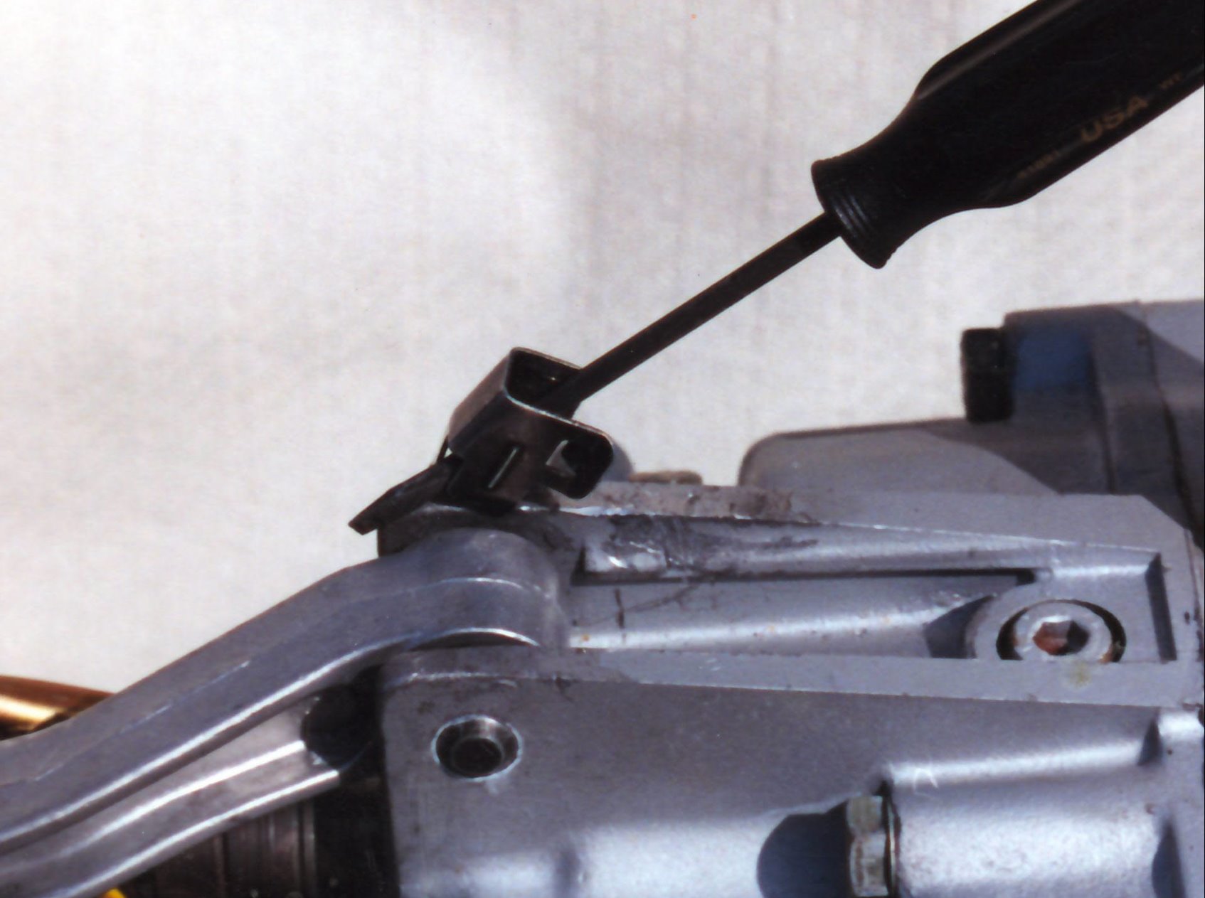
use a small flat blade screwdriver to pry the retaining band so that the pin can be released. Below is a round clip variant of the retaining clip

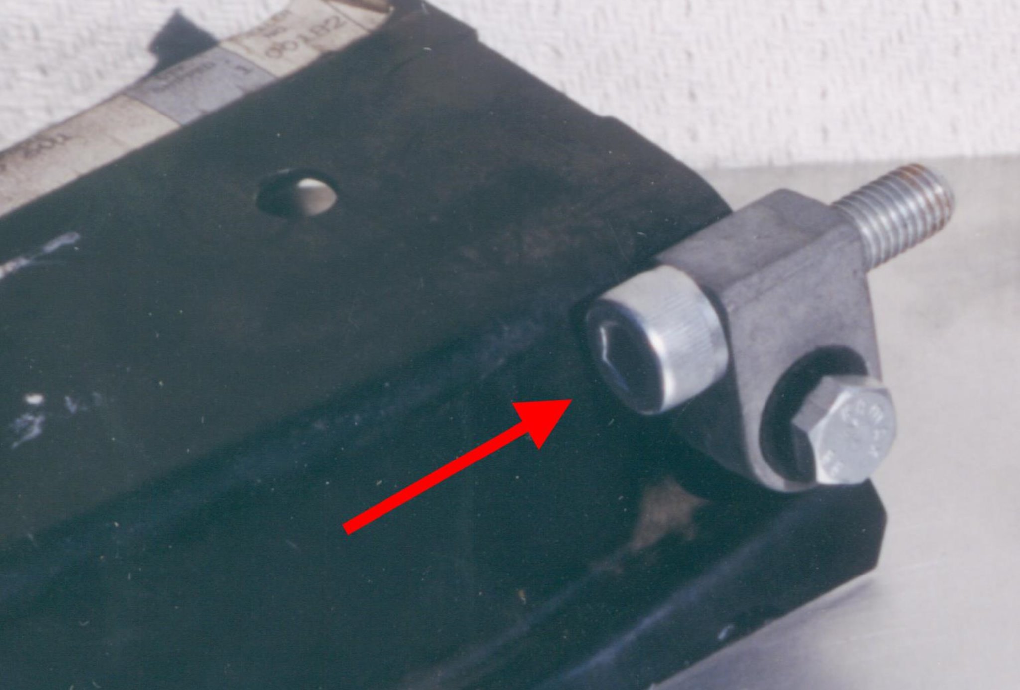
If you need to remove the shift arm and it is an aluminium shift arm, that arm is held by a pin sometimes referred to as a "jesus clip" that clip consists of a sheet metal retainer and a pin. the pin A goes through the transmission housing then through the shift arm bushing housing B and exists the transmission at point C. The sheet metal retainer rotates and the clip D engages the raised area E
To remove the clip slip a small screwdriver between the retainer sheet metal and the transmission, then leverage the screwdriver towards the centerline of the transmission effectively disengaging the sheet metal clip from the transmission body.
Now maintaining pressure, rotate the screwdriver up so that the sheet metal part of the clip clears the transmission body. Pull the pin out and release the clip. repeat the same procedure if you have a shift arm with 2 clips.
For a video of this procedure click here
If you have a sheet metal console, unscrew the bolts holding the aluminium isolation blocks to the transmission. Those are typically allen head bolts 8mm or 10mm hex.
Installation of the New Shifter

Compare the OEM Shifter to the AS Shifter
First make sure that the selector rod/coupler assemblies are equal in length
Compare the OEM Shifter to the AS Shifter
Then make sure that the hardened pin can slide in the coupler and that the foam pad is present inside the coupler.
Finally if you have a replacement AutoSolutions shift arm, make sure that the pin fits inside the bushing. Use sandpaper to clean the pin if needs be.
First install the selector rod/coupler assembly. Make sure that the foam pad inside the coupler is present. Compress the pad , Insert the pin and secure with the wire clip
Then install the shift arm if needs be. Reverse the jesus Clip procedure if you have an aluminum arm or bolt the arm to the transmission if you have a steel arm.
IMPORTANT:
Make sure to replace the isolation blocks for a steel shift arm or the rubber bushing if you are installing an aluminum arm
FRONT BUSHING INSTALL
1. Aluminum arm:
Coat the bushing in dishwashing liquid or any kind of lubricant such as vegetable oil and press the bushing in place using fingers or a hard surface such as a wood block if available
FRONT BUSHING INSTALL:
2. Steel Arm
These blocks bolt in place. Unbolt old locks and bolt new ones. Do not tighten until the arm is attached to the transmission. Once attached raise the arm in a near horizontal position and tighten.
FRONT BUSHING INSTALL:
3. Ultra kit
These bushing are very tight. the outer black urethane shell installs compressed between the transmission ears and is hard to fit Grease the bushing liberally using motor oil and force between the arm mounting ears. It is permissible to use any abrasive method to make the insertion easier. However the tighter the connection the better the end result.
These bushing also have a bronze sleeve on the inside that is exactly the diameter of the retaining pin. To align the bushing to the pin wiggle the arm into place while inserting an 8 mm bolt or similar diameter rod from the driver side ear through the bushing and out of the passenger side ear. Wiggle the bolt or rod to center the bushing.
Repeat the procedure using a larger bolt such as a 9mm bolt or 3/8th bolts or other similar diameter rod then finish aligning with a 10mm bolt or rod prior to inserting the pin.
In most cases you should be able to easily insert the pin after aligning with a 3/8 diameter rod. Sometimes the clip will go through the first transmission ear and into the urethane bonze sleeve but will resist coming through the passenger ear on the transmission. Use a 1/2 extension or any suitable bar as a makeshift lever to tap the pin through. then secure the clip by rotating it and allowing it to engage the transmission ear
FRONT BUSHING INSTALL:
IMPORTANT
If you have a steel shift arm or a pre 89 aluminum arm the front bushing can easily be installed first then the rear bushing bolted into place. However rear shift arm support bushings can be hard to release on later cars even with copious lubrication. If you elect to keep the rear bushing in place make sure to insert the rear of the shift arm into the rear bushing prior to securing the front bushing. Like this
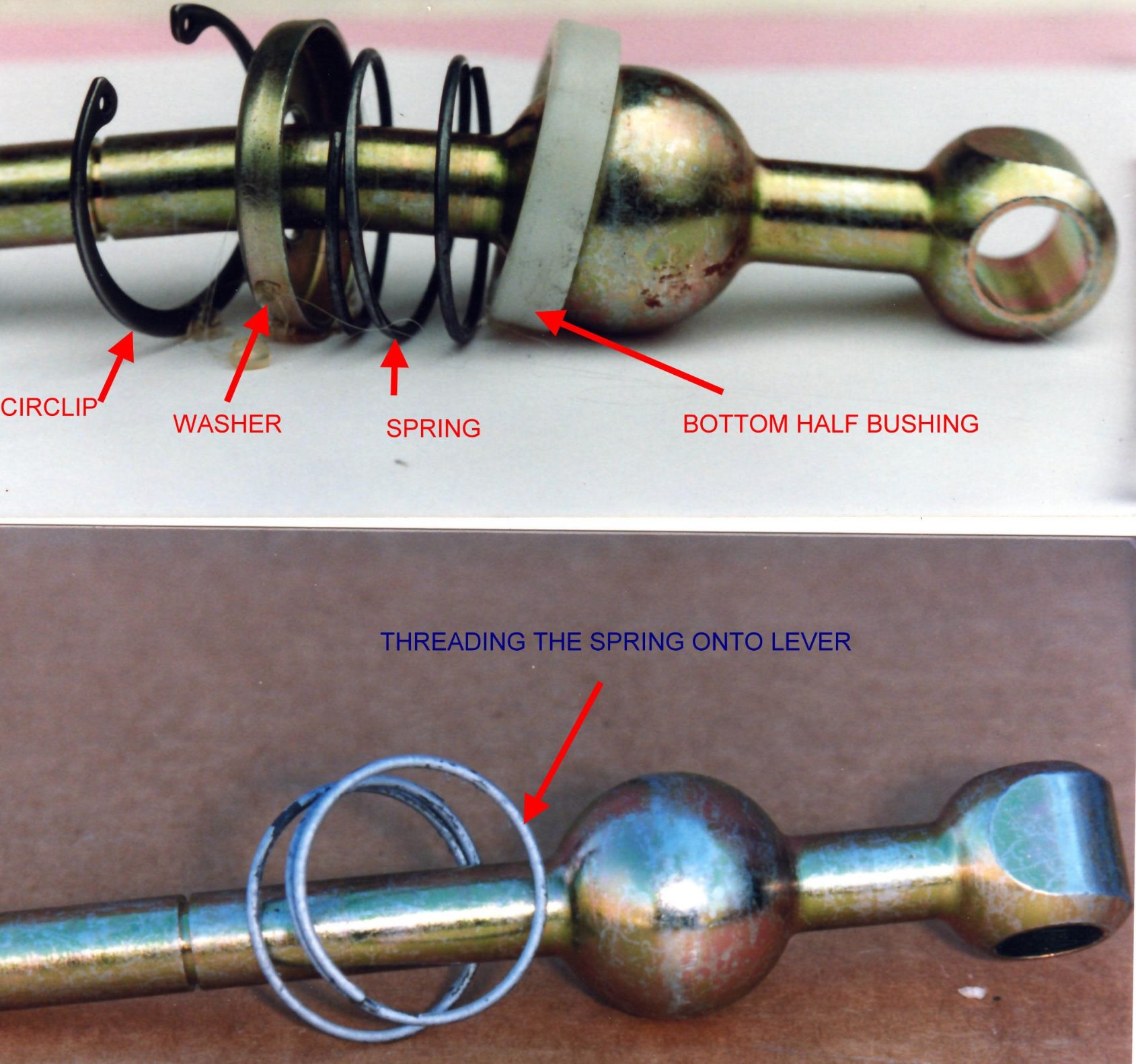
STEEL SHIFT ARM LEVER INSTALL : install the lever from inside the vehicle.your lever has a pivot ball that sits between 2 half bushings. The top half bushing is already installed on the AutoSolution lever. Also already installed is a flat washer. The lower half of the bushing is pressed in the shift arm. Leave the lower half of the bushing in shift arm. Unthread the compression spring from your old shift lever and thread it between the top half bushing and the flat washer on the new lever. Use the circlip from the old lever to clip the assembly in place.
Should you decide to replace the bottom half of the bushing or if your lever was supplied with a spacer, then press the bottom half out of the arm using a suitable punch.
Install the spacer first then a new bottom half bushing and clip the assembly to the shift arm. When using a spacer the spring is no longer used as the spacer takes its space.
ALUMINUM SHIFT ARM LEVER INSTALL : These use a one piece bushing. The old bushing is simply pushed onto the pivot ball from the bottom of the lever. The tabs on the bushing are aligned with the cutouts on the shift arm and the whole assembly is pushed into place until the tabs engage the cutouts and click in place. Sometimes it is necessary to apply downward pressure with a screwdriver to each tab so that it fully engages in the cutout

Tabs Lined up
Tabs Engaged
Push Down at Arrows to Fully Engage the Tabs
Reconnect Selector Rod to the Bottom of Shift Lever. Secure with Retaining clip.
IMPORTANT
1. Remember the Nylon washers that go on either side of the lever. One goes between the selector rod and the lever and the other between the lever and the retaining clip.
2. Use the provided e- clip making sure the flat side of the e- clip faces outwards or re-use the factory retaining clip.
3. Make sure the lever is properly oriented prior to reconnecting it to the selector rod. An improperly oriented lever will typically shift the pattern forward and to the right in most cars.
Install Shift Knob
If you have an earlier car with a screw on shift knob then it is a no brainer as the shift knob simply screws on clockwise as viewed from the top. Righty Tighty.
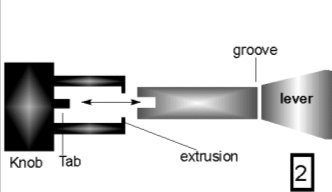
If you have a push on shift knob then simply rotate the shift knob on the lever. There is a tab inside the shift knob that will engage with the cutout on the lever. Once that tab engages the shift knob will drop on the lever a few mm or 1/4 of an inch. At this point rap firmly on top of the knob so that it can engage the groove in the lever. These knobs have plastic extrusions that will engage in the groove located on the neck of the lever. Don't forget to reconnect any wiring related to the shift knob illumination and make sure all the isolation foam and inner rubber boot are in place. Note that there is an arrow on the rubber boot that points to the front of the car.
Where installation of a particular element is different than its OEM equivalent
e9X, E8X,F80 and anything that has this type of lever
If your shifter lever comes already installed in the shift arm. Download
Need help installing the front of the carrier. Check this

you have a 2002 with a Close Ratio 5 speed or Overdrive 5 Speed or S14 engine
Your shifter is fine but your shift rail inside the transmission has quite a bit of slop. Click on the fix
Installing the triangulation on street or race car with a 265 Getrag 5 speed. Check this.